1. Tools needed for preparation:
Two feeler gauges, one vernier caliper, one depth gauge, one internal micrometer, one copper rod (¢65×300).


2. Method of adjusting screw clearance:
Picture (1):

1. First distinguish the main and auxiliary screws, look at the two screws from the rear to the front, and then install the pie, push the two screws into the barrel at the same time, and drive the positioning pins. Turn the mark of the screw to the upper fulcrum, tighten the big nut, and put all the spline sleeves of the two screws in place. At this time, do not rush to adjust the screw gap. You should first determine whether the two screws are in free motion. Only the two screws are free. The screw gap can only be adjusted correctly under the condition of movement (meaning that no matter the top plate is used to withstand the main screw or the auxiliary screw, the other screw can move back and forth). How to make the two screws reach a free-running state: Use the top plate to tighten the auxiliary screw or the main screw, whichever screw is the same, use the crowbar to move the other screw to see if it can move forwards and backwards. For example: Tighten the auxiliary screw, and the main screw cannot move forward and backward. This means that the shim of the main screw is too thick, there is no gap between the front and rear, and the twin screw is seized. Then loosen the auxiliary screw and tighten the main screw. , Toggle the auxiliary screw, the auxiliary screw can move back and forth, which proves that the shim of the auxiliary screw is too thin. From the above, the shim of the main screw should be repaired or the shim of the auxiliary screw should be repaired, generally plus or minus 0.5 About mm (the gap between the screw of Shenweida machine and the screw shall not be less than 0.3mm).
After trimming, tighten one screw and turn the other screw to see if the two screws are in free motion. If so, you can proceed to the next step, otherwise, make further adjustments.
illustrate:
(1) The “upper pivot” on the screw refers to the marks of the two screws.
(2) Big nut: refers to the connecting block that connects the distribution box and the barrel of the host.
(3) Big pie: refers to a fixed plate with two screws.
(4) Spline sleeve: refers to the connecting sleeve between the screw spline shaft and the distribution box spline shaft
2. Figure (2) and Figure (3) use a feeler gauge to measure the minimum clearance and maximum clearance of the seven and eight segments of the two screws, respectively, and calculate the serial momentum of the two screws. Methods of measurement and calculation:
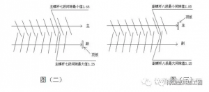
(1) Tighten the auxiliary screw with the top plate, and use the crowbar to move the main screw backwards. Use a feeler gauge to measure the minimum gap between the seven segments of the main screw to be 2.65mm, and then use the crowbar to move the main screw forward and use the feeler gauge. The maximum gap value of the seven sections of the main screw is 3.25mm, and then the maximum value is 3.25 to the minimum value 2.65=0.60mm, which is the series momentum of the main screw.
(2) Loosen the auxiliary screw and then tighten the main screw, move the auxiliary screw backward with a crowbar and use a feeler gauge to measure the minimum value of the eight-segment auxiliary screw to be 2.85mm, and then use the crowbar to move (forward) the auxiliary screw. For the screw, use a feeler gauge to measure the maximum gap value of the eight-segment auxiliary screw at 3.25mm, and then use the maximum-minimum value. Example: 3.25-2.85=0.40, which means that the series momentum of the auxiliary screw is 0.40mm
(3) Comparing the data obtained by the two screws, it is concluded that the series momentum of the main screw is 0.60-0.40=0.20mm larger than that of the auxiliary screw, which cannot satisfy the normal operation of the equipment. It is necessary to adjust the shim of the screw. According to the difference between the two screw series of 0.20mm, because it is a twin screw, it is necessary to calculate their average value: 0.20mm÷2=0.10mm, this 0.10mm is the main screw Or add a sub-screw? It should be added to the shim of the main screw and 0.10mm copper skin. Because the series volume of the main screw is larger than that of the auxiliary screw, the copper skin should be added to the shim of the main screw.
(The purpose is to equal the string momentum of the two screws)
In this way, the string momentum of the two screws is equal, and the threads of the two screws will not collide during the production process (because the gap between the main screws is too large, it is necessary to add or subtract 0.10mm of the auxiliary screw shim). Only one screw horn can be trimmed.
Note: Do not look at theoretical data in terms of padding, because we mainly look at the front and back movement range of the main and auxiliary screws. Many of our technicians have ignored this problem and only focus on data without looking at actual results. In the previous data (main screw 0.6mm, auxiliary screw 0.4mm), these two data refer to the string momentum of the main and auxiliary screws. The larger the string, the cushion should be added, and the smaller the string, the cushion should be reduced. Points must be noted.
3. What is the gap between the screw and the barrel? Such as the 65 model.
1. Description: Generally, the backward distance of the screw of the 65 machine is 6-8mm, and the gap between the screw and the barrel is 0.25-0.35mm.
55 machine is 5-7mm 0.20-0.30mm
45 machine is 4-6mm 0.15-0.25mm
And every time the screw retreats one millimeter, the gap between the screw and the barrel is 0.0215mm (single side). Let’s first choose how many mm the 65 model should move backwards. Because it’s the 65 model, I choose the two screws should move backwards 7mm. Then the gap between the two screws and the barrel is 7×0.0215=0.1505mm (single Side), then the total gap between the two sides should be 0.1505+0.1505=0.301mm, this data has been able to meet the production needs.
2. How can the two screws be moved back by 7mm, and how much should be added or removed from the two pads? Let us explain one by one below.
(1) The gap value of the seventh and eighth segments should be measured first, and the method of measuring the gap value of the seventh and eighth segments: Figure (4)
Tighten the two screws at the same time with the top plate, and use a feeler gauge to measure out the data of the seven and eight segments respectively, which are 2.20 and 2.30 respectively.
(2) Explanation of the gap value of the seventh and eighth segments: The gap value of the seventh and eighth segments is a safety guarantee value to ensure that the serial amount of the main and auxiliary screws does not change. As long as the gap between the seventh and eighth segments remains unchanged, the serial momentum of the two screws will not Change, the string momentum of the two screws does not change, so the gap between the two screws will not change.
(3) Loosen the splined key cover, top plate, and large nut. Use feeler gauges (two) to plug the gaps between the seventh and eighth sections to 2.20/2.30 respectively, and then tap the two screws with a copper rod to make the screw and the material There is no gap in the barrel, and the large nut is locked. The distance between the pad iron of the two screws and the two spline shafts of the distribution box is measured with an internal micrometer (Figure 5) respectively: main: 3mm, auxiliary 4mm.

Then it can be concluded that the main screw should retreat (the 65 machine mentioned above) 7mm 3mm=4mm and the shim of the main screw should be removed by 4 mm. Then the auxiliary screw should also use 7mm-4mm=3mm, and the shim of the auxiliary screw should be trimmed off by 3mm. In this way, it can be concluded that the two screws are retracted by “7mm” at the same time, and the gap between the barrel and the screw is 7×0.0215×2=0.301mm. If there is no distance between the two screws and the spline shaft of the distribution box, what should I do? The shim of the two screws should be removed first, and then the measurement is performed. The measured data minus 7mm is the remaining size of the shim.
Fourth, the calculation method and measurement method of the gasket of the two-screw pig iron sleeve
1. Use a feeler gauge to plug the seven and eight gaps respectively, which are 2.20/2.30 (same as the previous measurement), and then use a copper rod to lightly hit the main and auxiliary screws and the barrel without gaps, and put on the retaining ring (Pictured).

2. Use the depth gauge to measure the distance from the retaining ring to the pie. Example a=118mm, b=119mm. (Note: each screw needs to measure three points to calculate the average value)
3. Use the depth gauge to measure the thickness of the two pig iron sleeves respectively (as shown in the figure) C=82mm, D=84mm. (Pig iron sleeve is a fixed sleeve between the two screw retaining rings and the big cake. There is a screw seal ring inside, which is mainly used to convey the oil at the screw oil temperature)
